Control valves regulate the flow of a liquid or gas by opening or closing internal passages.
They form part of a control loop used to control a process. The control valves respond to instructions from the controller and adjust the internal openings accordingly.
Keywords: sensor, setpoint, trim, actuator, sealing class, tuning, proportional, integral, derivative.
Purpose of control valves
A control valve varies the rate of flow passing through itself.
The valve stem moves, altering the size of the passage and this increases decreases or holds steady the flow.
The control valve opening is altered whenever the process parameter being controlled does not equal the value it is meant to be (the set point).
Operation of a control valve
A control valve consists of three key components – the valve, the actuator and the controller.
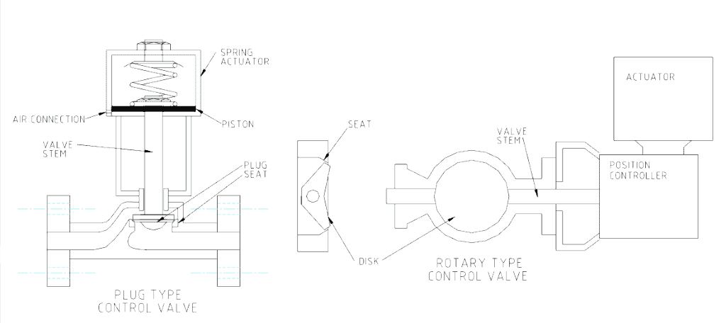
The valve can be one of two basic types. A plug and seat design, in which a plug is closed against a seat or a quarter turn valve in which a disc, ball or cone is turned against a seat.
The drawings below show the two types of control valves.
The actuator is used to move the valve stem.
They are usually air (pneumatically) or electrically driven. The controller calculates the size of the change to the valve internal passage to bring the flow to the desired rate.
The rate of flow through the valve depends on the pressure difference between the inlet and outlet.
To slow the flow the valve is closed which causes more back-pressure and a greater difference between the inlet and outlet pressures.
To increase the flow the valve is opened which reduces the back-pressure and the pressure difference across the valve.
Internals of a control valve
The portion of the valve that regulates the flow is known as the valve trim.
It consists of a fixed-in-place seat and the movable plug, disc, ball or cone.
The trim can be selected to create a variety of passage shapes that control the flow in deliberate ways.
Control valve tuning
The controller tuning dictates the way the valve responds to the changing process parameter.
Tuning of a control valve sets the speed and intensity of the valve response when the need for a correction is detected.
The controller contains internal logic that produces an output to the actuator to move the stem a predetermined amount.
This logic looks at:
- the size of the discrepancy between the set point and the
current value of the controlled parameter (Proportional)
- the length of time the discrepancy has been present (Integral)
- the speed at which the discrepancy has been changing
(Derivative)
and then determines how fast and how far to move the stem.
Once the position of the trim is altered the controller waits for the next sample signal from the sensing element to check the difference remaining to the set point.
The valve stem is moved and the flow altered until the difference between the setpoint and the actual value of the controlled parameter is within tolerance.
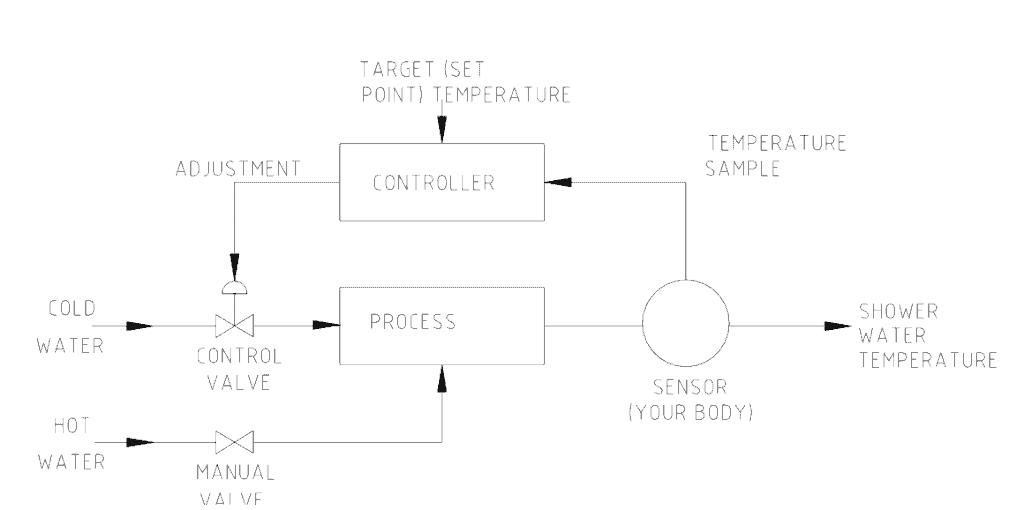
An example of tuning a control valve can be likened to a person under a shower adjusting the taps to get the water temperature right.
The sketch below shows the logic involved in controlling the water temperature.
If the hot water is first put on, the control valve becomes the cold water tap.
Your body senses the temperature of the water. If the water is too hot you open the cold water tap.
You wait a while (the time lag) to sense the effect of increasing the cold water flow. The cold water is adjusted until the temperature from the combined flows is just right.
Once the temperature is right the valves are left alone and the temperature is stable.
If a change occurs, such as someone doing the laundry with cold water, a drop in cold water flow to the shower occurs and the water temperature gets hotter.
You again sense the changing temperature and make the necessary adjustments.
In response, the cold water tap is opened further or the hot water tap is closed.
This whole process involved sensing the temperature and moving valve positions until the parameter under control (temperature) stabilized. A control valve works the same way.
Problems with control valves
Control valves may not properly regulate the parameter they are controlling.
If the process cannot be controlled product quality issues arise.
- Control valves can be sized too large. An overly large control valve is wasted money and is insensitive when fine adjustments are needed. Usually, control valves are one or two line sizes smaller than the pipe.
- A control valve can have excessive lag (react too late) because the sensor is located too far away.
- The actuator air supply may be low or leaks away and so produces insufficient force to move the stem.
- The control valve stem can become sticky if the packing is tight or product leakage causes binding of the stem.
Control valve sealing classification
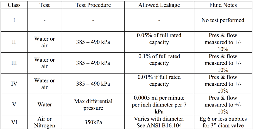
Metal seated control valves are classified into classes reflecting the quality of sealing.
The higher the valve class, the smaller the leakage rate allowed when closed; the finer the manufacturing requirements and the more expensive to buy.
Table 1 shows the various control valve sealing classifications.
Mike Sondalini – Maintenance Engineer
If you found this interesting, you may like the ebook Pumping Basics.


I may be training to work on the production floor later next week, and so learning more about the valves and how they work is very helpful. It’s good to know that tuning the valve sets the speed and intensity, as you said, and I’ll be sure to remember that if I need to do a correction on one of them. The fact that the controller has an internal logic that can figure out the proportional, integral, and derivative, as you said, is pretty impressive, too.