Semiconductor Integrated Circuits (ICs) can have millions of digital circuits which can translate to billions of transistors.
I know these numbers can be intimidating, but I assure you the challenges of testing ICs started in the mid-late 1970’s. Lots of effort has been put into Electronic Design Automation (EDA) systems and Design for Test (DFT) techniques to manage the development and application of digital circuit testing.
In the beginning these software programs and DFT techniques used the Stuck at Fault Model.
Intro to Stuck at Fault Model
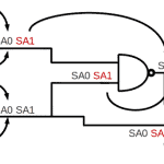
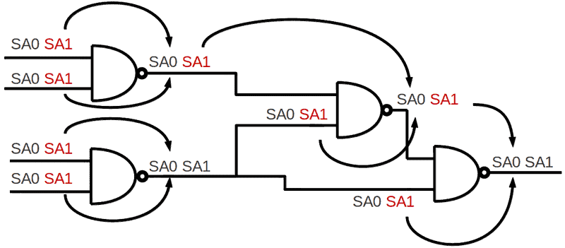
With a stuck at fault model you are applying a structural test approach. Instead of testing all combination of 1’s and 0’s to a VLSI device, you will test with a reduced set of test vectors. Stuck at Fault Models operate at the logic model of digital circuits. An input or an output can be Stuck at Zero (S@0) or Stuck at One (S@1) So let’s proceed and use three digital circuits (aka logic gates) to illustrate: Inverter, NAND, NOR. In CMOS technology, these logic gates can be found in most logic functions.
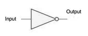
Inverter Logic Table
| A | D |
| 1 | 0 |
| 0 | 1 |
Inverter Stuck faults list: A S@0, A S@1, D S@0, DS@1
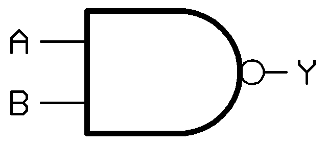
NAND Logic Table
| A | B | Y |
| 1 | 0 | 1 |
| 1 | 1 | 0 |
| 0 | 0 | 1 |
| 0 | 1 | 1 |
NAND Stuck faults list: A S@0, A S@1, B S@0, B S@1, C S@0, C S@1
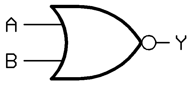
NOR Logic Table
| A | B | Y |
| 1 | 0 | 0 |
| 1 | 1 | 0 |
| 0 | 0 | 1 |
| 0 | 1 | 0 |
NOR Stuck faults list: A S@0, A S@1, B S@0, B S@1, C S@0, C S@1
Notice again the NAND and NOR gate have the same fault list. This makes sense because they have identical number of inputs and outputs. Yet they won’t be tested the same way.
Testing With Stuck at Fault Model
With a stuck at fault you apply a pattern (set of 1’s and 0’s) to the inputs of the logic gate such that you get a faulty response. So let’s start with the inverter. Suppose A is S@1. Easy test, you need to apply a 0. Now lets’ look at the output D stuck at 0, you need to apply a 0 to A. Table below tabulates the test pattern per S@ fault.
Inverter S@ Fault and Test Table
| S@ Fault | Test A | Pass D | Failing D |
| A S@1 | 0 | 1 | 0 |
| A S@0 | 1 | 0 | 1 |
| DS@1 | 1 | 0 | 1 |
| D S@0 | 0 | 1 | 0 |
Now while you there exist 4 faults to test you only need 2 tests as shown in the table below. This is commonly called fault collapsing.
Inverter S@ Fault Coverage of Tests
| A | Stuck @ Faults Detected |
| 1 | A-S@0, D-S@1 |
| 0 | A-S@1, D-S@0 |
NAND and NOR Stuck at Fault Model and Test
The same fault and test approach applies to the NAND and the NOR gate with the caveat that you consider two inputs. If you want to test a S@ fault at input A you need to apply a logical state at input B input that would “pass” the impact of input A. With a NAND you apply a 1 at B, and with a NOR you apply a 0 at B. Let’s look at a NAND on a S@ fault basis.
NAND S@ Fault and Tests
| S@ Fault
|
Test A | Test B | Pass Y | Fail Y |
| A S@1 | 0 | 1 | 1 | 0 |
| A S@0 | 1 | 1 | 0 | 1 |
| B S@1 | 1 | 0 | 1 | 0 |
| B S@0 | 1 | 1 | 0 | 1 |
| Y S@1 | 1 | 1 | 0 | 1 |
| Y S@0 | 1 | 0 | 1 | 0 |
| Y S@ 0 | 0 | 1 | 1 | 0 |
| CYS@ 0 | 0 | 0 | 1 | 0 |
So with the NAND a logic circuit with 2 inputs and 1 output has a bit more complexity. You need to pass defective input to the output to make it visible. At least, you have only 1 output to look at. You’ll notice that the table lists all possible input combinations of A and B to test Y-S@0. You only need one test. How do you choose? Well let’s consider fault coverage and the minimum tests needed for complete fault coverage. As shown in the table below for the NAND shows, for every test there’s a list of faults it can detect. You have 6 faults to detect and 4 possible test patterns (set of 1’s 0’s for A and B). You only need to apply 3 of the possible tests. Which test is unnecessary?
NAND S@ Fault Coverage of Tests
| A | B | Stuck @ Faults Detected |
| 1 | 0 | Y-S@0, B-S@1 |
| 1 | 1 | A-S@0, B-S@0, Y-S@1 |
| 0 | 0 | Y-S@0 |
| 0 | 1 | A-S@1, Y-S@0 |
That’s right, the 00 test vector which detects Y-S@0 is covered by two other test vectors. Note there’s an assumption- only one fault occurs at any one time. Often called single stuck at fault. We can go through the same steps for the NOR. I leave it to the reader to do the S@ to test table and provide you with the fault coverage table below. Like the NAND gate you only need 3 of the 4 possible tests to cover all 6 faults.
NOR S@ Fault Coverage of Tests
| A | B | Stuck @ Faults Detected |
| 1 | 0 | A-S@0, Y-S@1 |
| 1 | 1 | Y-S@1 |
| 0 | 0 | A-S@1, B-S@1, Y-S@0 |
| 0 | 1 | Y-S@1, B-S@0 |
Why Use the Stuck at Fault Model
So why did stuck at fault modeling come about? Turns out the first published paper arrived in 1959 nearly 6 years before Jack Kilby and Robert Noyce independently proposed the Integrated Circuit. Circuit complexity and the test time to apply an exhaustive list of tests became too time consuming. If you treat an integrated as black box with X inputs and Y outputs you could just apply all possible inputs and check that the correct output is applied. When X= 4 that’s 16 input patterns. When X=125 that’s ~4.26**37 input patterns. Yikes even if it only takes 1 nanosecond for each test you’re going to be testing for a very very long time.
If you know what’s inside the black box you can apply tests based upon fault models. This takes a structural test approach because you aren’t checking for functionality you checking that no faults exist. In the 1970’s EDA tools called automatic test pattern generators (ATPG) and fault simulators were created to manage test of LSI (Large Scale Integration). Development of EDA tools and DFT methods has evolved over the last four decades to enable efficient and quality testing of semiconductor devices with 1 billion transistors. The evolution of digital testing starts with the S@ model and has added models to reflect the defective behavior that occurs. With the Stuck At Fault model you need to keep in mind that it models one type of behavior which naturally has limitations. What is missing from the S@ model that needs to be accounted for with today’s devices?
Meanwhile remember testing takes time and thoughtful application,
Anne Meixner, PhD
Additional Reading:
My classmate Tom Storey’s thesis focused on a different fault model- Bridging faults in CMOS. I recalled that he included the first paper on S@ modeling in his thesis. He responded to my request for this reference. He wrote me, “This, by consensus, is the first usage of the term Stuck-at-Fault. “
R.D. Eldred, “Test Routines Based on Symbolic Logical Statements” Journal Assoc. Computing Mach., Vol 6(1), pp. 33-36, 1959.
There are numerous books on Digital/Logic testing and in a future post I’ll provide you list. Several electronics test conferences exist. I’m partial to the International Test Conference. Most conferences offer one to two days of tutorials which can give you a good overview of a test topic.
Leave a Reply