The Basics on How Fluid Flows in Pipes
A fluid is either a liquid or a gas. In industry, they are piped from storage to the point of use. Correct design and installation of the piping system minimises pressure loss and improves the behaviour of equipment and processes.
This article briefly explains what happens to fluids flowing through pipes.
The Pipe Wall
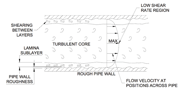
A fluid flowing through a pipe contacts the pipe wall. The pipe wall has surface roughness. The amount of roughness affects the drag on the fluid. Roughness is measured by the height of the projections sticking up from the pipe wall.
In the valleys between projections the fluid moves slowly. Above the projections it moves faster. The drag between layers tears, or shears, them apart and each layer moves at a different speed. The shear rate decreases as the distance from the wall increases. The velocity at the wall is zero and fastest at the center. This means the central core of the fluid exits the pipe first.
Friction and the Laminar Sub Layer
Because of friction caused by the pipe wall the fluid moves slower near the wall. This slow moving fluid is known as the laminar sublayer. In this layer the fluid slides over itself. The thickness of the sub layer can vary from tenths of a millimeter to several millimeters depending on the speed of the flow, the height of the wall projections and the fluid’s physical properties. The sublayer only develops in turbulent (fast) flows. At slow flows the sublayer blends in with the lamina (slow) flow in the pipe. Figure 1 shows the effect on flow velocity of the surface of a pipe wall.
Away from the pipe wall the flow is turbulent. In this area there are eddies and vortices moving randomly about the pipe from side to side and top to bottom. It is a region where confused lumps of fluid ‘tattle’ about their way along the pipe. Between the laminar and turbulent regions is a short transition zone as the flow changes to turbulent.
Viscosity and Density Effects
Liquids do not all behave the same. Blood has different flow characteristics than water. Paint flows differently to gasoline petrol. Liquids are categorised by their behaviours when undergoing shear. Those liquids that have a constant shear rate with change of velocity (like water) are called Newtonian (Newton first developed the mathematical explanation for the phenomenon). Those with shear rates that vary with changing velocity (like paint and blood) are Non-Newtonian. The shear rate is a measure of a fluid’s viscosity or slipperiness.
The density of a fluid affects its viscosity. Fluids with more mass per unit volume are heavier and require more energy to move them and shear less easily. A temperature rise decreases the viscosity and density of liquids.
The more viscous, or less slippery, a fluid the harder it is to get shearing between layers. The high viscosity prevents rapid velocity changes occurring between layers. The sub layer in viscous fluids is thicker than in low viscosity fluids.
Velocity Effects
At low speeds the whole flow across a pipe is laminar and the fluid slides over itself. As the speed becomes faster eddies start to form and cross the fluid layers. A transition from laminar to turbulent flow develops. At still higher velocities the flow in the core of the pipe becomes turbulent with swirling eddies throughout. Figure 2 shows where the various flow regions occur at a tank nozzle.
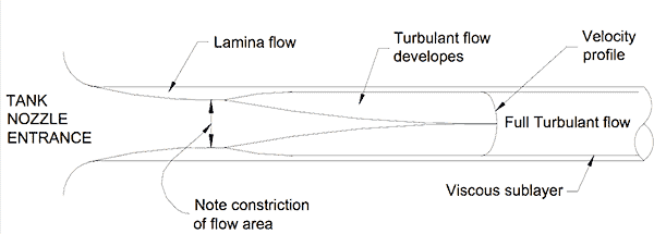
The laminar sub layer is always present against the pipe wall. But as the velocity rises the energetic swirling eddies begin to impact more deeply and the sub layer begins to thin. At still higher velocities the sub layer thins further and the taller roughness peaks stick into the turbulent region. Where the sub layer covers the roughness projections the wall is considered ‘smooth’. When the wall roughness pokes out of the sub layer the wall is considered ‘rough’. This means the same wall can be both smooth and rough depending on the fluid’s velocity.
Experiments have proven the pressure loss along a pipe with laminar flow is proportional to the velocity (p ∝ V) where as for turbulent flow the pressure loss is proportional to the square of the velocity (p ∝ V2). A slower flow permits a thicker sub layer and creates a ‘smooth’ pipe wall. This minimises the losses along the pipe. There is a very much greater loss of pressure in turbulent flow.
The pipe system designer has to strike a practical balance between increasing the pipe diameter to reduce energy loss and keeping the diameter small to lower installation costs.
Minor Losses in Piper Fittings
Elbows, bends, reducers, branch tees and flanges all cause individual minor pressure losses. When a fluid is forced to change direction, or go around a disruption, eddies are produced. These new twisting eddies interfere with the flow pattern and produce additional pressure losses.
The greatest pressure losses occur at sudden diameter and direction changes. Most of the loss occurs in the downstream eddy wake. When designing a pipe run gradually blend-in changes to the flow pattern.
Gas Flow
Unlike a liquid a gas is compressible and can be squashed. When a gas is compressed the density increases – as the pressure is released the density decreases. Gas flowing into a pipe starts at a pressure, temperature and associated density. The frictional losses along the pipe cause a pressure loss. If the gas is now at a lower pressure it must be at a correspondingly lesser density. (It is less squashed together than it was at the start.) This means the density of a flowing gas varies along the length of the pipe. The effect is greater at higher velocities.
For a mass of gas to enter a pipe an equal mass must leave the pipe. We know the density is continually thinning as the pressure drops along the pipe. One kilogram of less dense gas requires more space (volume) than the same weight of a more compressed gas. To get one kilogram of expanding gas, which is taking up more volume, out from the end of the pipe it must go faster than when it entered the pipe. Gas flowing through a pipe expands as the pressure falls and speeds up the further it travels along the pipe.
Expanding gas cools. This principle is used in refrigerators and air conditioners. A gas flowing in a pipe is expanding as the density falls. This is why compressed air lines are cool to touch and why water droplets collect in pneumatic valve actuators. The temperature has fallen low enough to condense the water vapour.
Mike Sondalini – Maintenance Engineer
If you found this interesting, you may like the ebook Process Control Essentials.
can we quantize/ recognize water flow pattern through pipe, if yes then how
look for example at
https://www.nrel.gov/docs/fy16osti/65441.pdf
They describe one possible way to model a fluid flow through a pipe together with associated assumptions and model properties.
which are the equations for a gas flow in a circular pipe that is permeable to another gas that is outside ? The problem is that of contamination of the inner gas flow by permeant outer gas through the pipe wall.
Very nice explanation Mr. Mike, thank you very much
For volumetric flow compensation, gas flow must increase with decrease in actual density. Is it correct?
Explained well .Thank you mr.
What external sensor/method can be used to measure the flow of water inside a pipe (iron/pvc). The important is sensor should be external to pipe, i.e. without cutting pipe and install in between.
Thanks .