Accendo Reliability

Your Reliability Engineering Professional Development Site

  • Home
  • About
    • Contributors
  • Reliability.fm
    • Speaking Of Reliability
    • Rooted in Reliability: The Plant Performance Podcast
    • Quality during Design
    • Way of the Quality Warrior
    • Critical Talks
    • Dare to Know
    • Maintenance Disrupted
    • Metal Conversations
    • The Leadership Connection
    • Practical Reliability Podcast
    • Reliability Matters
    • Reliability it Matters
    • Maintenance Mavericks Podcast
    • Women in Maintenance
    • Accendo Reliability Webinar Series
  • Articles
    • CRE Preparation Notes
    • on Leadership & Career
      • Advanced Engineering Culture
      • Engineering Leadership
      • Managing in the 2000s
      • Product Development and Process Improvement
    • on Maintenance Reliability
      • Aasan Asset Management
      • AI & Predictive Maintenance
      • Asset Management in the Mining Industry
      • CMMS and Reliability
      • Conscious Asset
      • EAM & CMMS
      • Everyday RCM
      • History of Maintenance Management
      • Life Cycle Asset Management
      • Maintenance and Reliability
      • Maintenance Management
      • Plant Maintenance
      • Process Plant Reliability Engineering
      • ReliabilityXperience
      • RCM Blitz®
      • Rob’s Reliability Project
      • The Intelligent Transformer Blog
      • The People Side of Maintenance
      • The Reliability Mindset
    • on Product Reliability
      • Accelerated Reliability
      • Achieving the Benefits of Reliability
      • Apex Ridge
      • Metals Engineering and Product Reliability
      • Musings on Reliability and Maintenance Topics
      • Product Validation
      • Reliability Engineering Insights
      • Reliability in Emerging Technology
    • on Risk & Safety
      • CERM® Risk Insights
      • Equipment Risk and Reliability in Downhole Applications
      • Operational Risk Process Safety
    • on Systems Thinking
      • Communicating with FINESSE
      • The RCA
    • on Tools & Techniques
      • Big Data & Analytics
      • Experimental Design for NPD
      • Innovative Thinking in Reliability and Durability
      • Inside and Beyond HALT
      • Inside FMEA
      • Integral Concepts
      • Learning from Failures
      • Progress in Field Reliability?
      • R for Engineering
      • Reliability Engineering Using Python
      • Reliability Reflections
      • Testing 1 2 3
      • The Manufacturing Academy
  • eBooks
  • Resources
    • Accendo Authors
    • FMEA Resources
    • Feed Forward Publications
    • Openings
    • Books
    • Webinars
    • Journals
    • Higher Education
    • Podcasts
  • Courses
    • 14 Ways to Acquire Reliability Engineering Knowledge
    • Reliability Analysis Methods online course
    • Measurement System Assessment
    • SPC-Process Capability Course
    • Design of Experiments
    • Foundations of RCM online course
    • Quality during Design Journey
    • Reliability Engineering Statistics
    • Quality Engineering Statistics
    • An Introduction to Reliability Engineering
    • Reliability Engineering for Heavy Industry
    • An Introduction to Quality Engineering
    • Process Capability Analysis course
    • Root Cause Analysis and the 8D Corrective Action Process course
    • Return on Investment online course
    • CRE Preparation Online Course
    • Quondam Courses
  • Webinars
    • Upcoming Live Events
  • Calendar
    • Call for Papers Listing
    • Upcoming Webinars
    • Webinar Calendar
  • Login
    • Member Home

by Mike Sondalini Leave a Comment

Orifice Plate Meter Flow Measurement

Orifice Plate Meter Flow Measurement

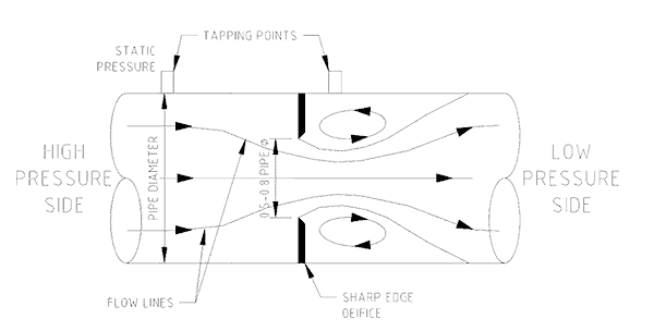
Orifice plate meter flow measurement. An orifice meter is a circular piece of metal plate placed between flanges in a pipe. In it is a square-edged round hole machined 0.5 to 0.8 pipe diameter in size. Pressure tapping points are placed either side of the plate at specified distances. The orifice causes a flow restriction and produces a pressure drop from one side of the hole to the other. The amount of pressure difference is proportional to the flow of fluid through the hole. The flow is calculated from the pressure difference and flow areas using accurate mathematical formulas.

Keywords: differential, static pressure

Effect of a restriction on fluid flow

When an object is put in the way of a flowing fluid (gas or liquid) in a pipe its presence obstructs the passage of the fluid. The fluid is forced to go around it. The flow diversion requires energy to power the motion and it is supplied from the fluid by its pressure falling as it squeezes past.

Figure No. 1. Orifice Plate Flow Meter.

The smaller the hole, the less that can get through it, and the greater the back-pressure in the pipe. That is how a faucet (a tap) controls the flow of water into a drink cup when it is opened. Just cracking the tap open produces a trickle. The high back-pressure in the pipe forces a small amount of water out of the tiny opening. As the tap is opened further, the hole gets bigger and the flow increases. The back-pressure in the pipe falls as the restriction is removed.

By knowing the size of the hole and the pressure difference from one side to the other it is possible to calculate the flow through the hole. An orifice plate flow meter uses the differential pressure principle to determine the flow. Figure No. 1 shows a cross-section view of an orifice meter with its pressure tapping points and stylised flow lines.

Static Pressure and Velocity Pressure

The pressure in a pipe of still fluid and the pressure in the same pipe with the fluid now moving are different. If a pressure gauge were mounted on the pipe it would read a higher pressure when the fluid was still than when it was flowing through the pipe. When a fluid is in motion the static pressure drops and the velocity pressure rises.

An example of static pressure is the pressure of the air in a room with the windows slightly open while outside there is a howling gale. If you go into the gale you would feel the pressure of the wind on you. That pressure is the velocity pressure of the moving wind. At the same time you would experience the static air pressure acting on you. On the windward side you would experience the static pressure plus the velocity pressure. Behind you there would only be static pressure (less a small amount of vacuum pressure). The static pressure is all around you, whereas the velocity pressure is only in the direction of the wind.

The same situation develops in a pipe full of fluid. Where the static pressure is high, velocities are low and where velocities are high static pressure is low (Recall the change in back-pressure in the kitchen pipes as the tap is closed and opened).

Measuring pressure across the orifice

In order to read only static pressure in a pipe the tapping hole must not be exposed to the velocity component of the flow. Usually a pressure gauge is mounted in a hole drilled through the wall, square to the wall. At the inside wall of a pipe the velocity is zero and only static pressure is present. 

An orifice plate flow meter uses static tapping points located at either side of the orifice. By convention the upstream static tapping is one pipe diameter up from the orifice and the downstream tapping is half a pipe diameter from the orifice at the location of the ‘vena contracta’ where the flow lines are most narrow.

The pressure difference between the two points is proportional to the flow and once the pressure difference is known it is put into an equation to find the velocity. From the flow velocity and cross-sectional areas of pipe and orifice, the volume of product flowing can be calculated.

Limitations of orifice plate meters

The accuracy of an orifice plate flow meter depends on the square edged remaining round and sharp. Wear or damage will produce errors in the pressure reading. It is also necessary to insure that no partial blockages occur upstream of the orifice that produce changes to the flow profile and pressure gradient. Blockages can occur in the sensing lines from the orifice to the transmitter or pressure gauge. The position at which the meters are located should be where the flow pattern in the pipe is straight and no turbulence exists.

Mike Sondalini – Equipment Longevity Engineer

Reference: Elementary Fluid Mechanics, Fifth edition , J K Vennard, R L Street, John Wiley & Sons.


We (Accendo Reliability) published this article with the kind permission of Feed Forward Publishing, a subsidiary of BIN95.com

Web: trade-school.education
E-mail: info@trade-school.education

If you found this interesting you may like the ebook Centrifugal Pump Problems & Answers.

Filed Under: Articles, on Maintenance Reliability, Plant Maintenance

About Mike Sondalini

In engineering and maintenance since 1974, Mike’s career extends across original equipment manufacturing, beverage processing and packaging, steel fabrication, chemical processing and manufacturing, quality management, project management, enterprise asset management, plant and equipment maintenance, and maintenance training. His specialty is helping companies build highly effective operational risk management processes, develop enterprise asset management systems for ultra-high reliable assets, and instil the precision maintenance skills needed for world class equipment reliability.

« The Russian Concorde … and why you haven’t heard of it
Taking on Unnecessary Project Risk »

Leave a Reply Cancel reply

Your email address will not be published. Required fields are marked *

Article by
Mike Sondalini
in the
Plant Maintenance series articles provided courtesy of Feed Forward Publications and Lifetime Reliability Solutions.

Join Accendo

Receive information and updates about articles and many other resources offered by Accendo Reliability by becoming a member.

It’s free and only takes a minute.

Join Today

Recent Articles

  • test
  • test
  • test
  • Your Most Important Business Equation
  • Your Suppliers Can Be a Risk to Your Project

© 2025 FMS Reliability · Privacy Policy · Terms of Service · Cookies Policy