Shaft alignment on pumps. Shaft misalignment is one of the most common reasons for bearing and mechanical seal failures. Rotating misaligned shafts produce vibration and complex fluctuating radial and axial loads that lead to breakdowns. Shaft alignment is a precision maintenance requirement that requires exacting care and detail and if not performed will cause much production down time.
Keywords: axial alignment, laser alignment, dial indicator, soft foot, shaft coupling.
What readers will learn in this article.
- Why shaft misalignment causes equipment failures.
- The correct accuracy for satisfactory alignment.
- The common causes of misalignment and their remedies.
- The proper shaft alignment process from start to finish.
Misaligned shafts are the single greatest reason for failure of rotating equipment and connected components. When misaligned shafts are coupled together each shaft rotates about a different centre. The shafts have different orbits. If the positions in the orbits are not directly opposite each other the coupling is distorted. The coupling reacts to the distortion by pulling or pushing each shaft.
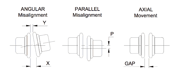
The axial, radial and bending forces developed by the ‘push- pull’ action, and the resulting non-circular shaft motion, is transferred through to bearings, shaft seals and, in pumps, to the mechanical seal. The motion that causes the most damage is the axial movement of the shaft. Figure 1 shows the types of misalignment
In order to prevent rapid failure of equipment the shafts must be purposefully aligned to within very close tolerances.
| Machine Speed | Max Offset at Machine Feet | Max offset at Coupling Centreline |
|---|---|---|
| Up to 1500 rpm | 0.050mm (0.002″) | 0.025mm (0.001″) |
| Over 1500 rpm | 0.025mm (0.001″) | 0.013mm (0.0005″) |
Table 1 shows alignment tolerances recommended by specialists after compiling equipment reliability data over many years and industries. Figure 2 shows an overhead view (plan view) of how Table 1 is applied.

This approach of aligning the whole machine guarantees parallel shafts and accurate coupling alignment.
The common practice of measuring between and across the coupling faces can produce a coupling within alignment tolerance but with backends on both machines still skewed.
THE CAUSES OF MISALIGNMENT
To prevent misalignment becoming a serious cause of equipment failure it is necessary to understand why it occurs so it can be corrected. Table 2 lists the most common causes of misalignment and explains what to do in each case.
| Cause | Remedy |
|---|---|
| Insubstantial foundations, bases and hold down bolts. | Concrete foundation mass must be 5-times the mass of the equipment it supports. This is usually only possible if the plinth is formed in the floor. Base plates must be thick and stiff to prevent distortion when the equipment applies torque. Typically thicker than 20 mm (3/4”). Hold down bolts must be bonded to the concrete and not just held in place by friction. Hold down bolts must stop the equipment flexing. On 2.2 – 11 kW drives use 16 mm diameter bolts, from 15 – 75 kW use 20 mm bolts, for 100 kW and above use 25 mm bolts. |
| Machine components damaged, poorly made and worn. | Make sure looseness in bearings that cause shafts to rattle and rotate off centre is taken-up. Replace bent shafts. Bore couplings on-center making sure the bore is parallel with the hub and square with the face so there is no run-out (wobble) as it turns. The bore machined into a coupling must be central to within 0.02 mm (0.001”). |
| ‘Soft-foot’ (‘spongy’ support) at the machine feet. | ‘Soft-foot’ is the term used to describe the situation where the machine support feet do not all make complete and even contact with the base plate or frame on which it sits before the hold-down bolts are tensioned. It is easy to pull a foot down with the hold-down bolts but the result is a bent and twisted machine with bent and twisted internal parts. A machine bent out of shape will fail before it should. Use 316 stainless steel shims (plastic is too soft and mild steel– rusts) under each foot so the foot is positioned ‘naturally’ and the hold down bolt can keep the foot in its ‘natural’ location. |
| Excessive forces generated by attachments (such as piping). | A machine is also pulled out of shape by attached items of plant (e.g. misaligned piping). The alignment between machine and attachment must be accurate enough to allow the connecting bolts to slip into the bolt holes by-hand. Any leverage that is required (including using hand tools) to line-up parts will produce a bent and twisted machine. |
| Foot locator has moved or warped. | If the support for a machine foot is no longer contacting and holding the foot in its ‘natural’ position it will need to be repaired and reinstated. At times concrete plinths are broken, hold down bolts come loose, mild steels. |
THE ALIGNMENT PROCESS
There are four distinct and separate phases when aligning pumps – the pre-alignment check, the rough-in alignment, the precision alignment and the record keeping.
The pre-alignment check involves inspection and planning. Check foundation and baseplate condition for deterioration, strength and vibration dampening. Baseplates must be supported under their entire area by grout. Put air vent holes in the base plate if necessary.
The pump’s rotating components and coupling must be to the manufacturer’s tolerances.
- Check and measure tolerances for bearings and seals and make-good where out-of-tolerance.
- Check the shaft run-out for bent shafts and loose bearings (maximum of 0.1 mm (0.004”) for 0 – 1500 RPM and 0.050 mm (0.002”) for 1500 – 3000 RPM).
- Measure the coupling for off-center bore; insure the part that transfers the drive torque is in good condition.
Check for ‘soft foot’ by using dial indicators against each support foot and loosening-off one hold-down bolt at a time. Install or remove shims to provide support for the foot in its ‘natural’ position. Continue checking each foot till the movement upon release is less than 0.05 mm (0.002”).
Check misalignment of pipes connecting to the pump. After making safe, loosen-off the flange’s bolts and see if you can move them by hand without any leverage. Until each bolt ‘just drops-in’ the alignment to the pump is not correct.
Cut and modify the pipe until the alignment accuracy matches the bolt hole clearance so the bolts slip-in. The best way is to bring the pipe to within one meter of the pump. At the pump fit a gasket and bolt on a short flanged spool. Then field-weld a spool in the remaining gap. There are no short cuts to getting stress-free alignment.
The final preparatory step is to insure the machine can be moved enough at each foot to make alignment adjustments. Bolts need sufficient clearance to permit movement. Jacking screws may need to be made and attached by drilling and tapping the baseplate or base frame. Back off the jacking screws after aligning. Use one 4-mm (3/16”) thick steel washer under bolt heads or nuts to prevent ‘cupping’ the washer into the bolt hole and moving the pump out of alignment when tightened down.
The rough-in alignment involves bringing the pump and drive shaft coupling halves square and in-line. Start with 3 mm (1/8”) of shims under each foot with the hold down bolts centered. Using a straight edge across the coupling, jack and shim the feet and retighten bolts till the coupling halves are within 0.5 mm (1/32”) parallel offset and 0.5 mm/100 mm diameter angularity vertically and horizontally. Don’t insist that one machine stays stationary, look for the common line that gives the least movement for each machine.
Unless the equipment is precision aligned it will not deliver its full working life. To get precision alignment there are only three methods – laser, reverse dial indicators and rim & face dial indicators. The use of each method requires training and cannot be covered in this article. (For more information e-mail us at info@trade-school.education).
Finally record what was done so the next alignment is quicker. Note down, sketch and file the ‘as found’ measurements from datum points, ‘soft foot’ conditions and corrections, shaft and coupling run-outs, adjustment moves and the final shaft alignment data and tolerances.
The whole process can take 8 – 16 hours the first time a pump is aligned. But aligning the pump the next time should take about 3 – 4 hours.
If you use sub-contractors for alignments get your own people to do the entire work prior the precision alignment. Be sure the contractor is competent.
An alternatively to precision alignments which is worth considering is the use of ‘C’ (imperial) or ‘D’ (metric) frames (Much like a bell housing.) between pump and motor.
Mike Sondalini – Maintenance Engineer
If you found this interesting, you may like the ebook Bulk Materials Handling Introduction.
Leave a Reply