What you will learn from this article.
- How forces are distributed through an object.
- Force diagrams are used to represent forces on an object.
- Position and direction of a force determines the type of stress.
- How to redistribute force in a structure.
Why don’t you fall to the ground when you sit in a chair? Why doesn’t the roof fall in on top of you? We don’t expect these sorts of things to happen. But at times chairs fail and people fall to the ground and at times roofs fall on people. When structures are put under sufficient stress they will fail.
Forces in Structures
A structure is anything solid. When an object is solid it can take a load. When a load is applied to a structure it is stressed. The type and extent of the stress depends on the amount of load, the position of the load, the direction of the load, the shape of the structure and the properties of the material in the structure. A structure must be designed to take all the stresses created by the loads it is to carry.
The ‘A’ frame in Figure No. 1 is a structure under load. Let us say that the load is a workman with his tool kit. The ‘A’ frame supports a walkway and the man is walking to his next job. The weights of the man, his tool kit and section of platform above the frame total 200 kg. We will observe the effects of the force transmitted through the frame.
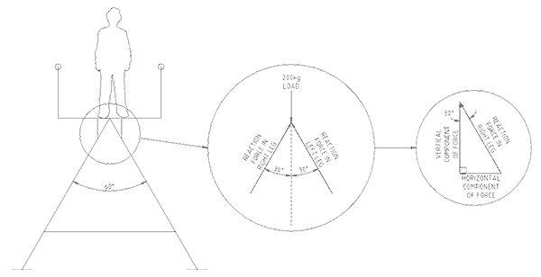
We first draw the frame on paper as a single line diagram and then apply the load to the frame. The line-diagram is a representation, a symbol, of the actual frame. We do not yet know the cross- sectional shape and size of the frame members. The members could be round or square solid bar, a pipe, a rectangular hollow section, an angle iron or an I-beam. Nor do we know what materials to use. We could use butter, plastic, wood, steel, concrete or aluminium. The choice of material and shape will come out of our investigation and it will depend on the stress it can handle.
Force Diagrams
To determine the size and direction of the forces in each member we replace the single-line diagram members by imaginary force lines that represent the members. At the top connection of the ‘A’ frame two members come together. This connection is shown as a force diagram in the exploded view in Figure No. 1. The two members equally share the weight of the man, tool kit and walkway. The connection is in equilibrium, that is, in a state of balance, with upward forces matching downward forces.
The direction of weight is always towards the center of Earth’s gravity. But each of the two legs taking the weight point away from the Earth’s center of gravity by 30o. Force cannot be transferred through open space but only through a solid structure. The forces in the legs can only be in the material of the legs. This is shown in the force diagram by the lines at 30o to the load line.
The proportion of weight in each leg is calculated using trigonometry. The triangle of force shown in the second balloon Figure No. 1 show the vertical and horizontal force components that make up the load in the right leg.
Since the downward and upward forces must be equal for the frame to be in equilibrium and not collapse, we put the downward forces equal to the upward force but in opposite directions. The equation can be written as –
200 kg = Fleft leg x Cosine 30o+ Fright leg x Cosine 30o
At the top connection each leg experiences 115.5 kg weight through its material. To convert this weigh to a force it must be multiplied by gravity, which on Earth is 9.81 m/sec/sec (say 10 m/sec/sec for simplicity of multiplication). The force in each leg is 1150 Newton (A Newton = 1 kg x 1 m/sec/sec).
Forces Cause Stress
A force acting on a solid produces stresses in the solid. Stress is defined as the force acting on an area square to the direction of the force. Its formula is
Stress = Force / Area (Newton/meter x meter)
Its unit of measurement is the Pascal (Pa) and one Pascal equals a
force of one Newton over one square meter of area.
The formula presents three options to handle stress. The first is to reduce the size of the force, the second is to increase the available area over which the force can act and the third is to use materials with a higher breaking stress than the stresses the load produces.
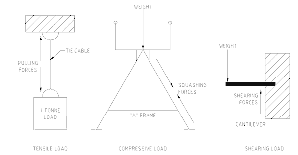
There are three common types of stress. The first is a tensile stress and is produced when a force pulls a thing apart. The second is a compressive stress and results when a force is acting to squash a thing together. The third type of stress is a shear stress and is the result of a force producing a tearing action through the object. Figure No. 2 shows examples of the three types of stress.
The position and direction of the force determines which stresses occur. Shear stress causes the greatest problem in engineering materials. In selecting the type of material and its size for the ‘A’ frame, all three stresses have to be determined. Once the maximum amount of each type of stress is know the correct material type and cross-section can be chosen to handle the stress without failing.
Redistributing Forces
Figure No. 3 shows a work place situation. A flange is welded to a pipe used as an agitator shaft in a tank. The paddles at the bottom of the tank wobble as they turn and the shaft is bent from side to side. The weld between the flange and shaft is subjected to the highest stress concentration and has been known to fail by cracking. This is a situation where the amount of weld cross-sectional area available to take the load is not sufficient to handle the combined effect of the load itself and the metal fatigue produced by the fluctuating stresses from the shaft wobble as it turns.
To lower the stresses at the weld it is necessary to share and spread the load over more area. One option is to add gussets to the flange and shaft as shown in the second drawing of Figure No. 3. Another option would be to user a a larger diameter pipe. A third option would be to use a material that can take higher stress before it fails.
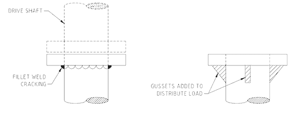
The gussets provide more cross-sectional area for the loads to act over by taking the loads away from the weld and redistributing them along the pipe and across the flange.
If faced with situations where parts and equipment are failing from stresses produced by high loads or fatigue situations, look at ways to increase the area over which the load is applied.
Mike Sondalini – Equipment Longevity Engineer
References: PP Benham & FV Warnock, Mechanics of Solids and Structures, Pitman International
JL Meriam, Engineering Mechanics Vol. 1 Statics, John Wiley & Sons.
If you found this interesting, you may like the ebook Process Control Essentials.
Leave a Reply